We designed and implemented a 2-axis, gesture-controlled camera platform based on a PIC32 microcontroller that maps the orientation of the user’s hand to the camera. It is able to support a relatively large camera system, orient the camera accurately, and respond quickly to user input.
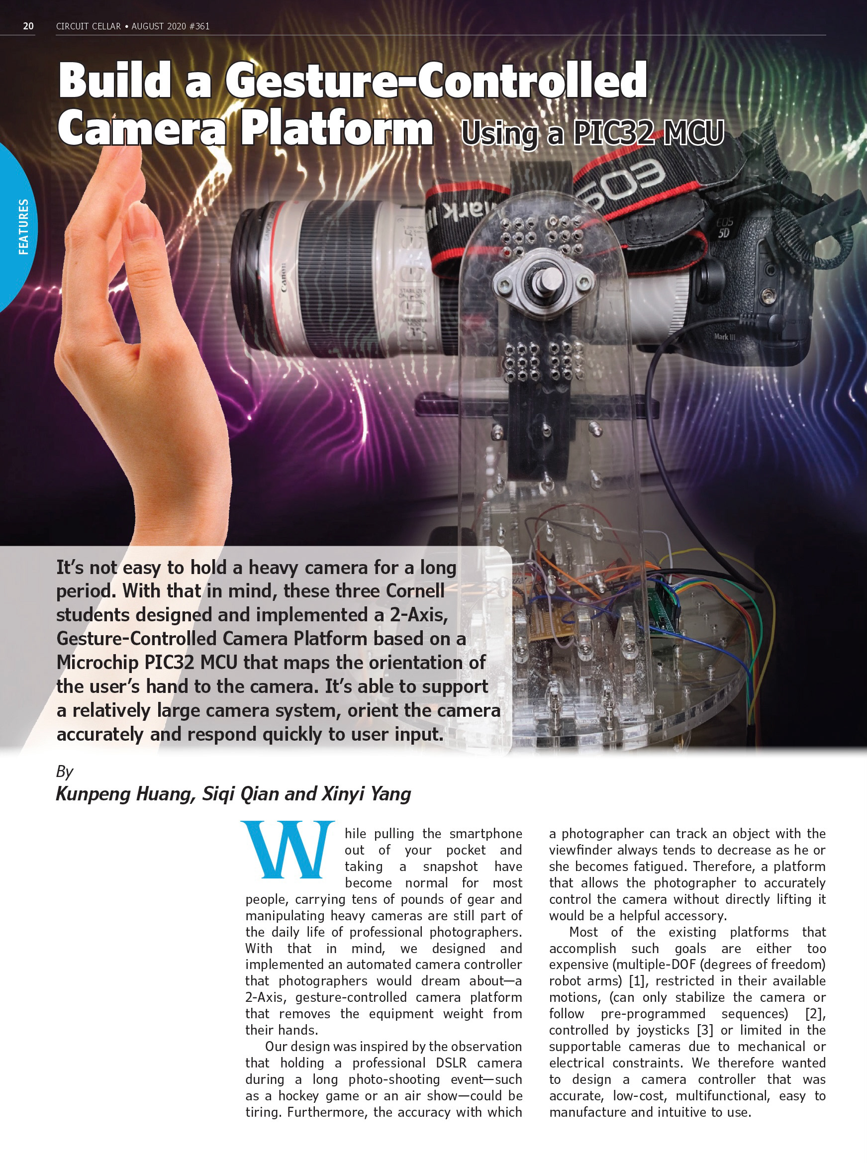
While pulling the smartphone out of your pocket and taking a snapshot has become a norm for most people, carrying tens of pounds of gear and manipulating heavy cameras are still part of the daily life of professional photographers. With that in mind, we designed and implemented an automated camera controller every photographer would dream about - a 2-axis, gesture-controlled camera platform that relieves the burden from their hands.
Our design was inspired by the observation that holding a professional DSLR camera during a long photo-shooting event, such as a hockey game or an air show, could be very tiring. Furthermore, the accuracy with which the photographer can track an object with the viewfinder always tends to decrease as he or she becomes fatigued. Therefore, a platform that allows the photographer to accurately control the camera without directly lifting it would be a helpful accessory.
Our 2-DOF gesture-controlled platform can point the camera in any direction within a hemisphere, based on spherical coordinates. It is capable of rotating continuously in the horizontal direction (yaw), and traversing close to 180 degrees vertically (pitch). It can support a relatively large camera system (more than 3kg in total weight and 40cm in length), orient the camera accurately (error less than 3 degrees), and respond quickly to user input (transverse 180 degrees in under 3 seconds). In addition to orienting the camera, the system also has simple control functionality, such as allowing the user to auto-focus and take photos remotely, which is achieved through DSLR’s peripheral connections.
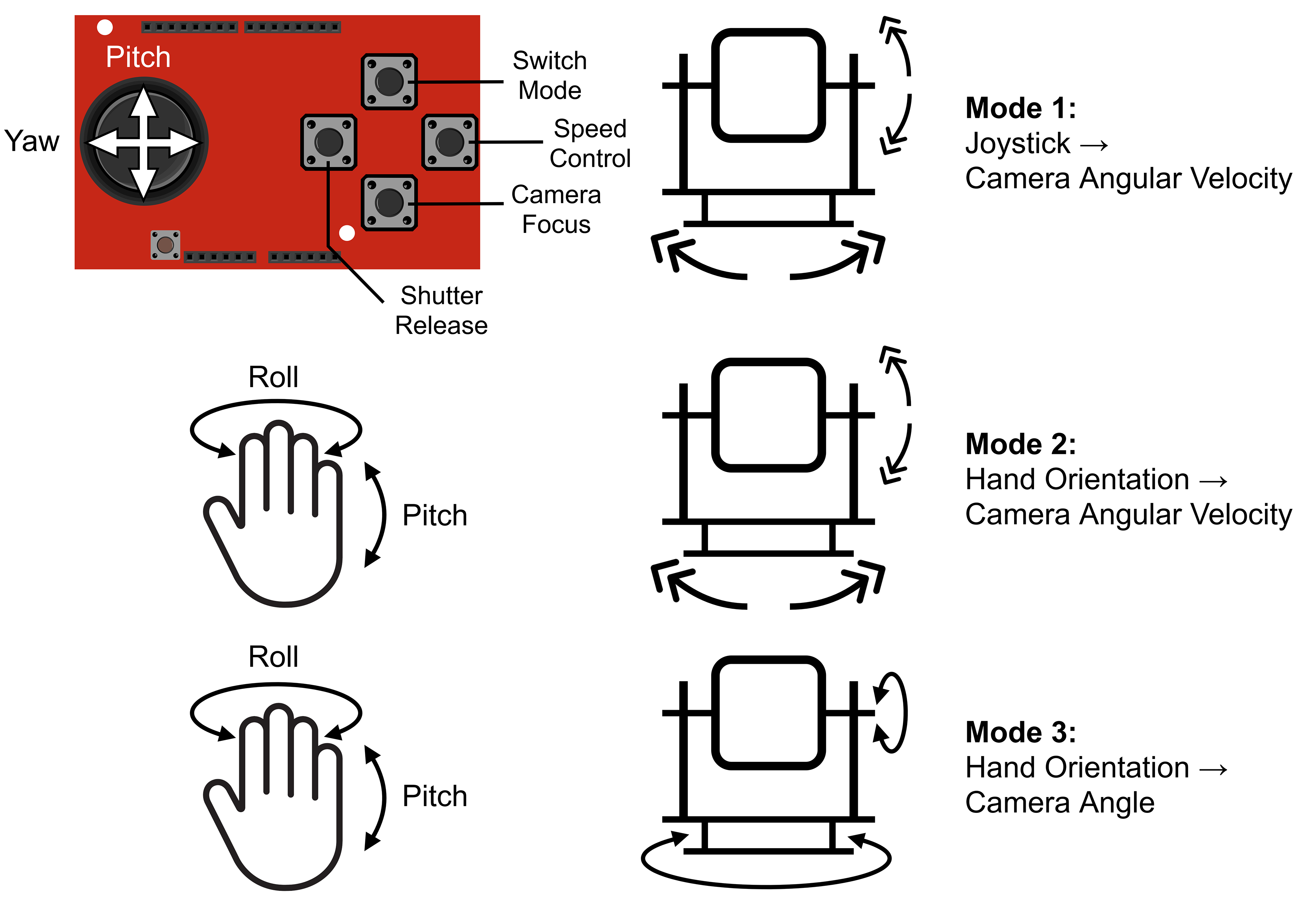
For the user interface, our design supports three user input modes. The first uses a joystick while the other two use an inertial measurement unit (IMU). In the first mode, the x- and y-axis of a joystick are mapped to the velocities of the camera in the yaw and pitch directions. A gamepad-style SparkFun Joystick Shield is used as the controller. The Joystick Shield also has buttons for focusing the camera, releasing the shutter, adjusting the panning speed, and switching control modes. In the second mode, the roll and pitch angles of the user’s hand are mapped to the velocities of the camera in the yaw and pitch directions. The third mode maps the angles to the angular position of the camera in yaw and pitch.
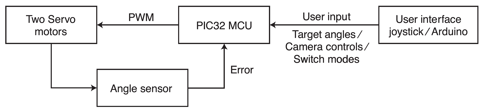
The overall logical structure of the platform. The flowchart shows the relations between the MCU, user interface, actuation, and feedback mechanism.
The figure on the left shows the overall logical structure of our design. Two servo motors actuate the camera and a Hall effect sensor measures its horizontal angle. The MCU takes inputs from the user to determine the target orientation of the camera, possibly with commands to switch control modes. Then, based on the error between the target position and current position given by the angle sensor, the MCU sends PWM signals to the servo motors, with the goal of reducing the error.
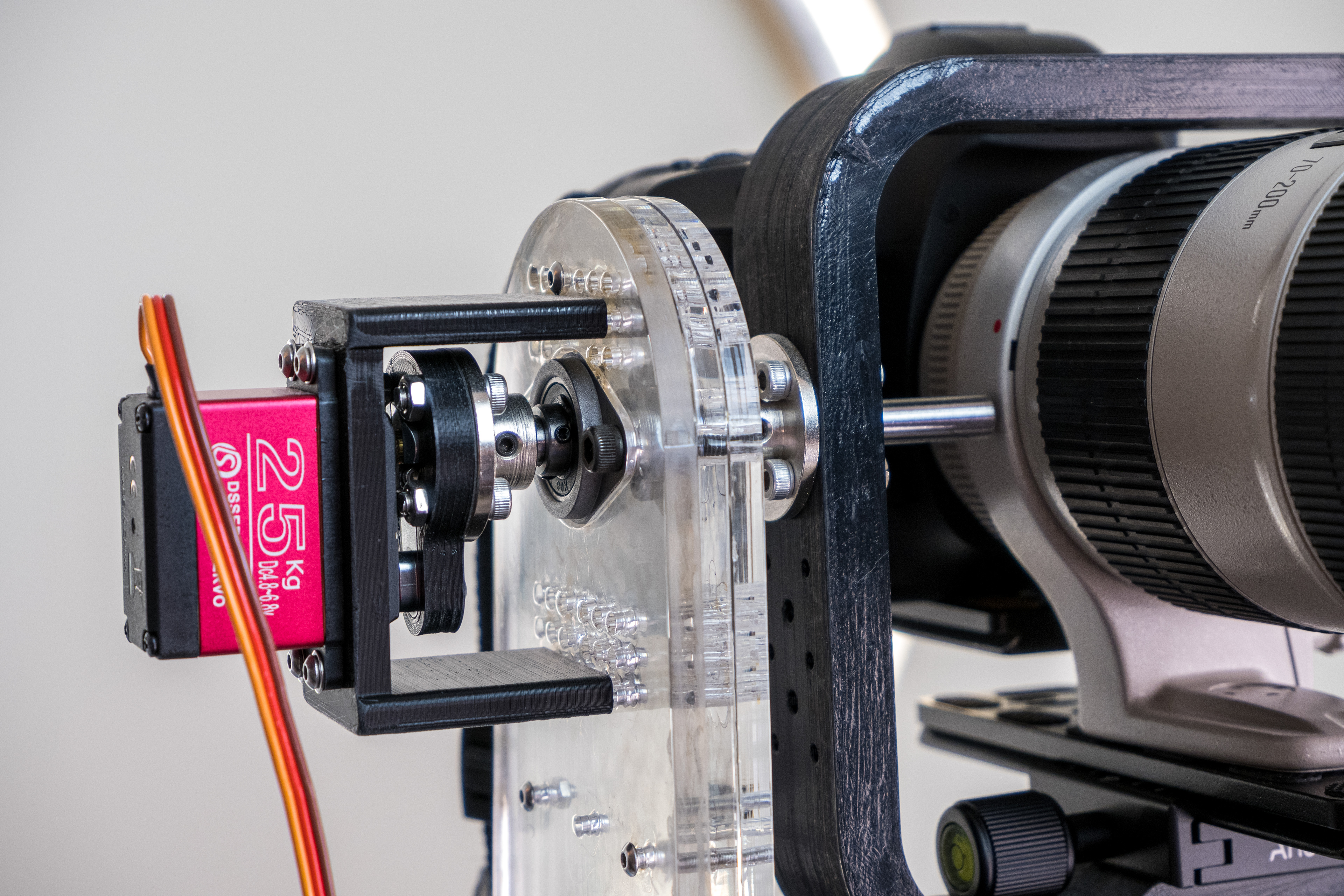
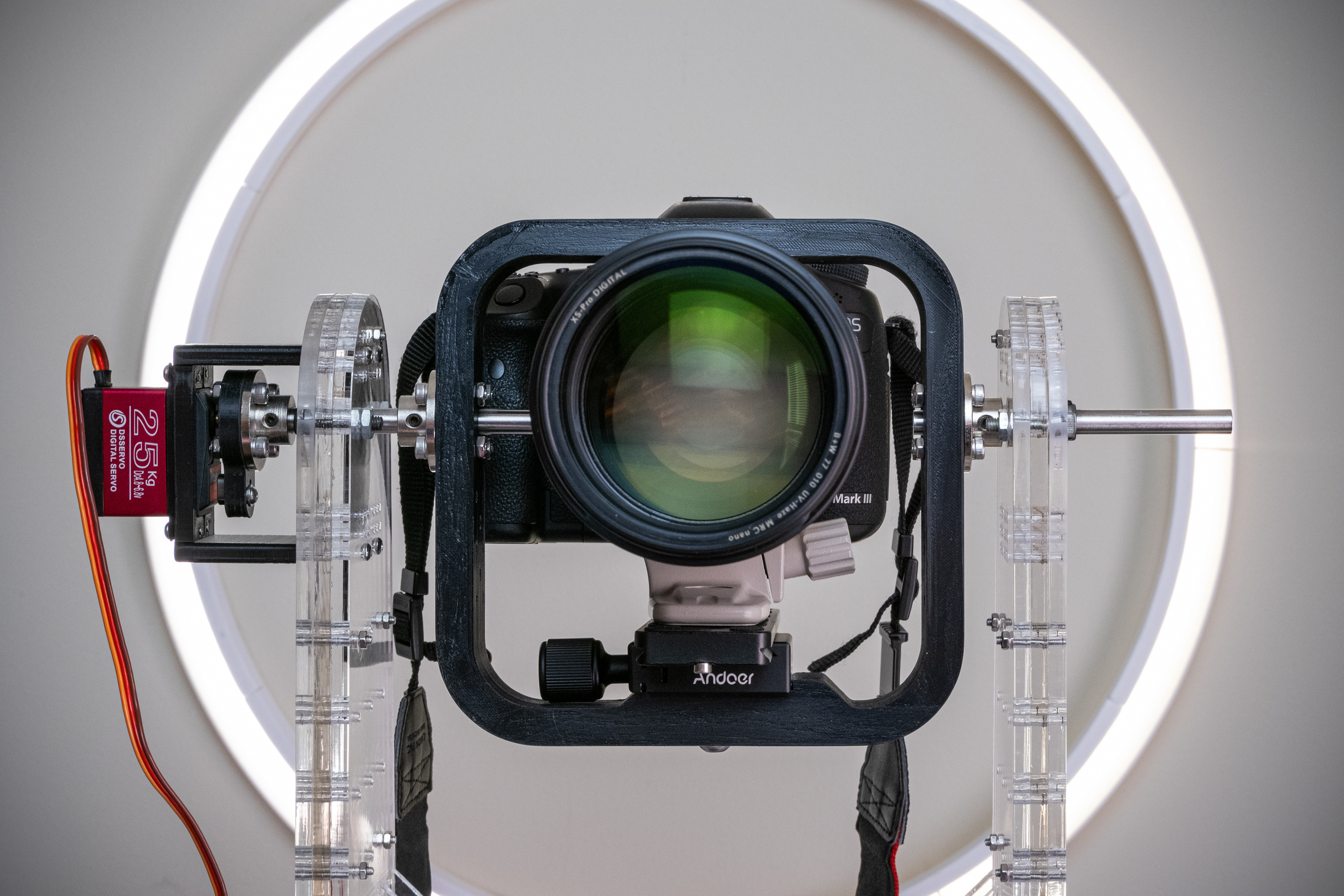
Top Servo, along with the vertical stand and 3D-printed camera bracket. The servo and camera bracket are linked together through a series of shaft couplers.
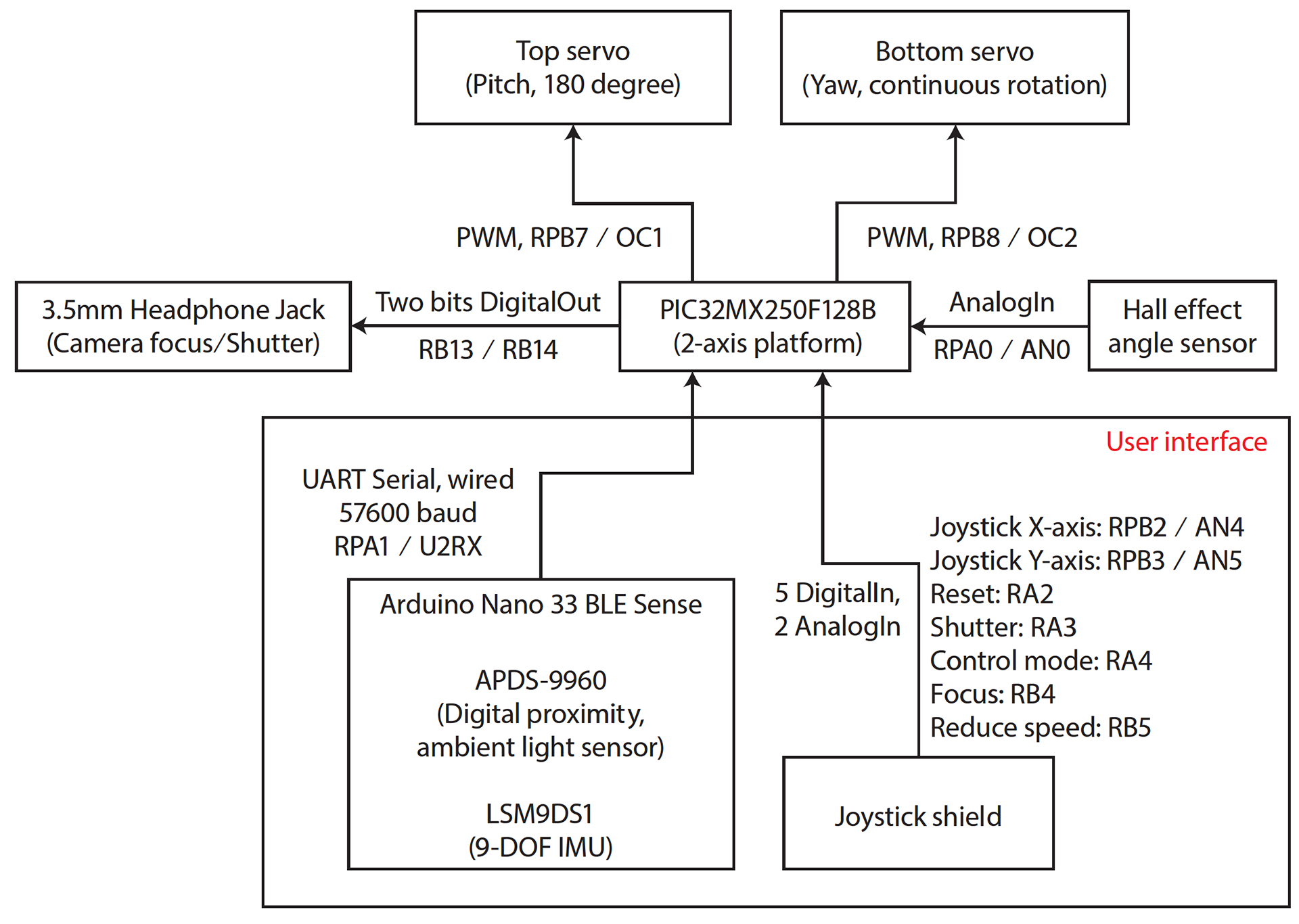
The connections and communication protocols between components. The arrows indicate the direction of data transmission. The large rectangle represents the user interface, which contains the Arduino Nano and the joystick shield.
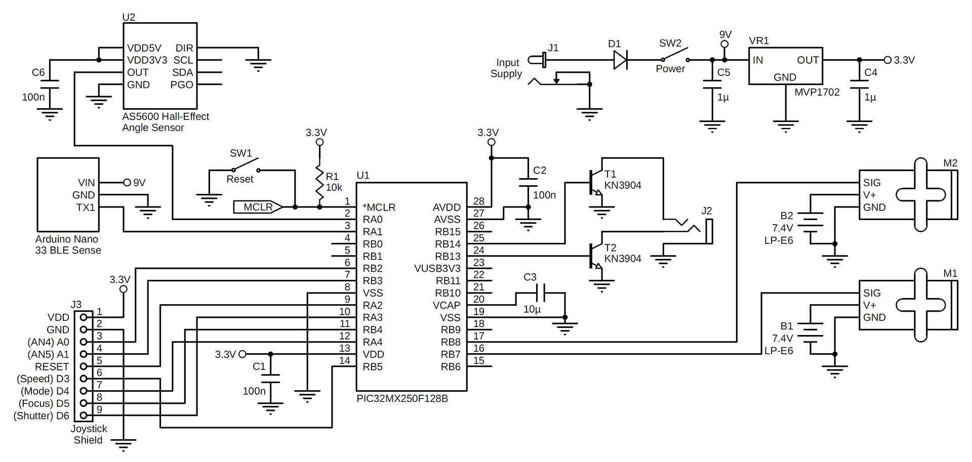
The complete schematic diagram for the circuit of the platform. The components on the development board include the voltage regulator, the PIC32 microcontroller and its peripherals. The LP-E6 batteries and servos are shown in pairs on the right side.
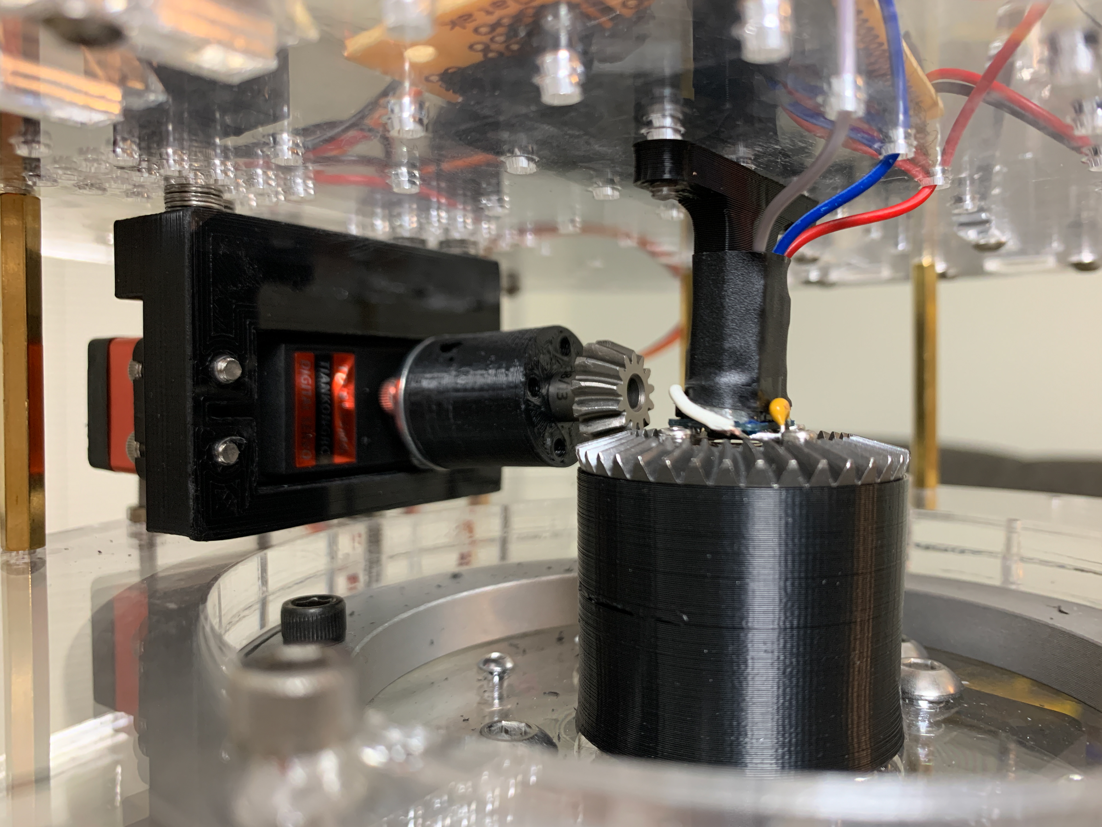
Continuous rotation servo, along with the bevel gears and Hall effect sensor. The larger bevel gear is affixed to the inner ring of the bearing, while the servo is attached to the outer ring through the acrylic plates and brass spacers.
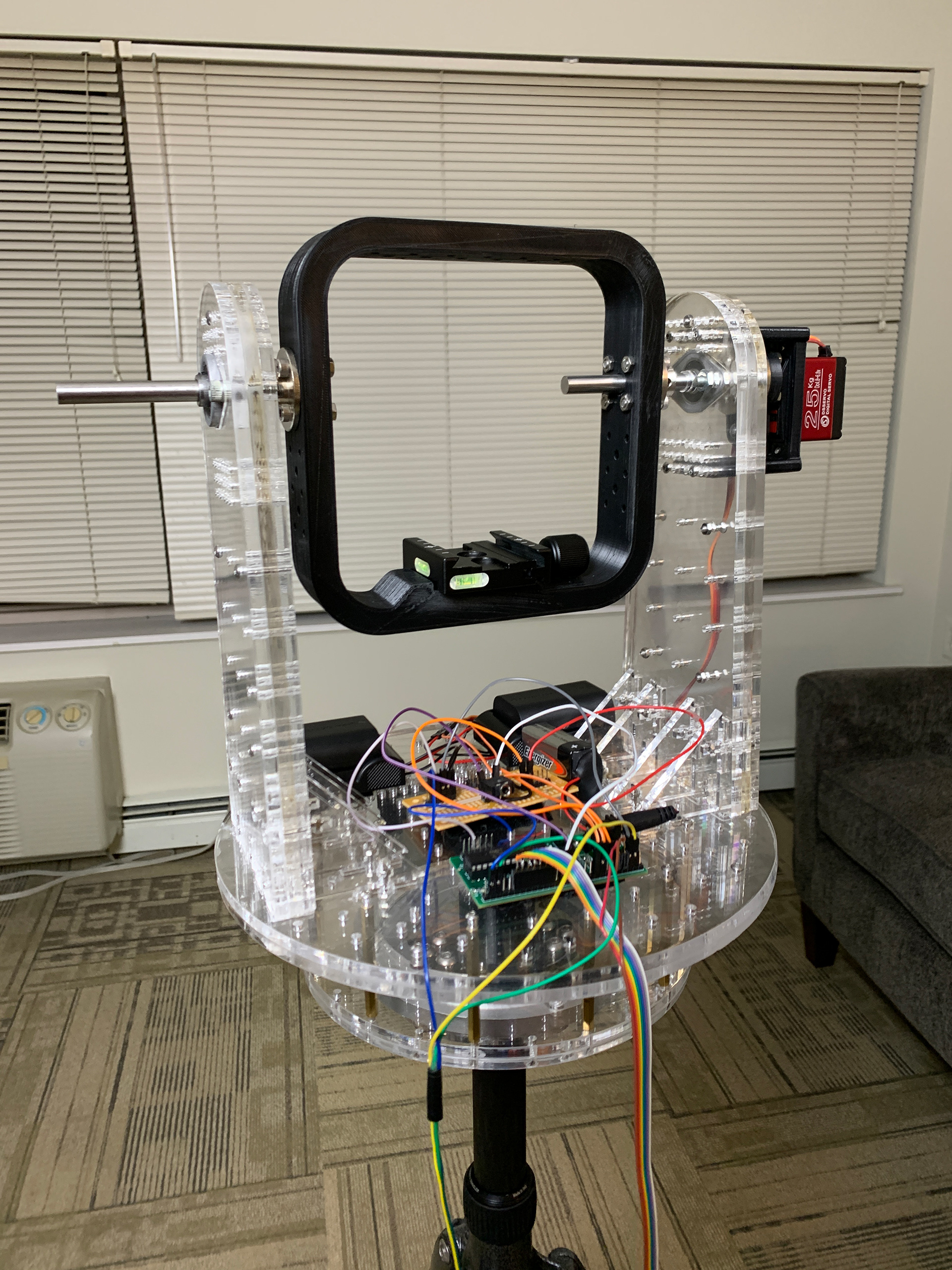
Front view of the finished platform assembly without the camera. All the circuit boards and batteries are mounted on the horizontal plate to minimize interference with the camera during rotation.
Huang, K., Qian, S., Yang, X. (2020, August). Build a Gesture-Controlled Camera Platform using a PIC32 MCU. Circuit Cellar, (361), 30-37. (Link to Circuit Cellar Article)